Trigon Fire Safety’s Karl Wallasch discusses the application of fire engineering on a smoke shaft design for a listed building’s hotel refurbishment.
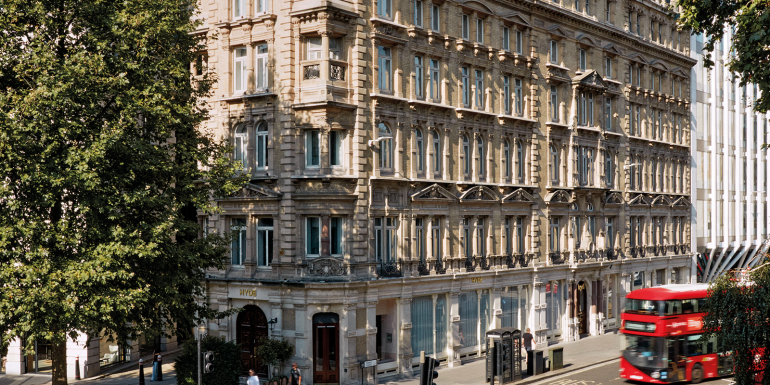
Built in 1874, 15 Old Bailey (next to the law courts) was once known as the Spiers & Pond Hotel and was the first ever hotel in London to have electric lighting. In the early 1900s it was remodelled into 64 serviced offices. By 2024, this Grade II listed building was transformed again, from offices back into a hotel with 110 bedrooms, a fitness centre, a restaurant and a speakeasy bar in the basement.
The renovation included extensive upgrades as well as a change of use, while considering the building’s heritage and design. There were also significant considerations to meet the fire safety regulation requirements for the seven-storey building. The following fire safety strategy uses fire engineering techniques (also known as performance-based design). A key focus was on using computational fluid dynamics (CFD) modelling for the smoke shaft design.

Smoke ventilation system of firefighting shaft
Approved Document B (ADB) recommends that a firefighting staircase and a firefighters’ lift should be approached from the accommodation through a firefighting lobby. For firefighting shafts, ADB refers to the guidance in BS 9999. Both the firefighting stair and lobby should be provided with a means of venting smoke and heat by following clause 27.1 of BS 9999. As per this clause, firefighting lobbies should be provided with smoke control systems by means of either a pressure differential system, a mechanical smoke ventilation system or a natural smoke ventilation system. Fire engineering techniques (also known as performance-based design) were applied.
The proposal for this project was to provide a mechanical smoke extraction system to serve the firefighting lobbies at basement, ground and first- to sixth-floor levels, with smoke extraction at ground-floor level via the external wall onto Green Arbour Court. The extract location would typically be located at roof level, so that smoke is extracted upwards however, due to space restrictions this was not a feasible option. The proposal for the seventh floor was to allow for natural smoke ventilation in the lobby via an opening to roof level.
In accordance with standard guidance, where mechanical smoke extract is being used, the system should be designed to demonstrate equivalent or better conditions in the staircase than would be provided by a natural smoke shaft solution, thereby conforming to the recommendations of BS 9999 and as described in BRE Project Report 79204.
BS 9999 states that the primary objective of the system should be to maintain smoke-free conditions in the staircase during both means of escape and firefighting operations. It is therefore considered that the key criteria for acceptance should be that the conditions are no worse in the staircase enclosure.
CFD modelling
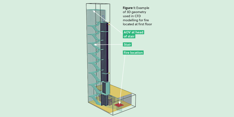
In order to provide a comparative study between the proposed mechanical system and a natural solution, designed in line with the recommendations of BS 9999, the performance of both systems was evaluated using CFD modelling (see Figure 1). Provided the agreed model demonstrated an equivalent, or better, performance compared to the natural solution, it would be considered to meet the functional requirements of the Building Regulations 2010.
As part of the approval process, the building control body involved an independent third-party reviewer for the aspect of the CFD modelling. The design team engaged with both at an early stage of the development of the initial fire safety when it was identified that fire engineering (in form of CFD modelling) would be applied.
Detailed discussion took place about the proposed approach, methodology and general assumptions to be used in the CFD modelling study. Only after agreeing on the approach and key parameters was the detailed CFD modelling conducted. After completing the CFD modelling and report, further discussions with building control took place – these led to a comprehensive final report for building regulations approval.
Natural smoke shaft solution
Recommendations for natural venting include:
- smoke shaft area of 3.0m²
- lobby vent located near the ceiling
- lobby vent to open based on detection of smoke in the corridor; and
- automatic opening vent at the shaft head.
Mechanical smoke shaft solution
The mechanical smoke extract system has been provided with ‘lobby vents’ between the mechanical extract shaft and the lobbies at each floor level. The lobby vents were located as close to the ceiling as is practicable and at least as high as the top of the door connecting the lobby to the stair well.
Upon the detection of smoke in the common corridor, the lobby vent, head of stair vent and fans associated with the mechanical smoke extract system would initiate the ventilation afforded to the protected lobby. The lobby has been provided with a pressure flow switch, designed to vary the extract rate of the mechanical smoke extract system based on the pressure detected in the firefighting lobby.
Unlike a typical smoke extract system, the proposed system was designed to discharge smoke via the external wall at lower level as opposed to discharging the smoke upwards and at roof level. This is due to the constraints created by the existing structure and limited plant space at roof level. Therefore, the fan was located at the mezzanine level between the ground and first floors.
A number of considerations played an important role in the CFD modelling:
- fire scenarios and locations: fire locations at sixth floor level, first floor and basement level
- reasonable worst case fire scenarios: worst case during means of escape phase as well as firefighting phase
- software: Fire Dynamics Simulator by National Institute of Standards and Technology Version 6
- cell sizes: 10x10x10cm
- leakage rate through doors and lifts: vary between 0.01 – 0.02m2
- door opening and closing: scenario depended on the scenario considered ie means of escape or firefighting access
- fire size: 4m2 fire size with 500 kW/m2 to achieve a 2MW fire (steady state); and
- steady state: modelling a steady state 2MW fire allows a direct comparison to be drawn between the proposed mechanical and natural smoke ventilation.
Further reading
- Building Regulations 2010
- Approved Document B: Fire Safety – Volume 2: Buildings other than dwellings, 2019 edition
- BS 9999: 2017, Fire safety in the design, management and use of buildings – Code of Practice, British Standard Institution
- BS 7974:2019, Application of fire safety engineering principles to the design of buildings – Code of Practice, British Standard Institution
- The SFPE Guide to Performance-Based Fire Safety Design b.link/SFPE_design
- BRE Project Report 79204: Smoke shafts protecting firefighting shafts: their performance and design, Building Research Establishment
- Fire Dynamics Simulator by National Institute of Standards and Technology pages.nist.gov/fds-smv
- CIBSE Guide E – Fire safety engineering 2019
The results
The CFD report showed that the mechanical system performs at least as well as a natural ventilation system during escape and firefighting. The following key items were considered during this review:
- heat release rate for each fire scenario
- visibility (m) in stair, lobby and corridor
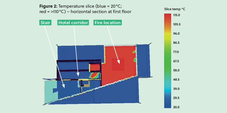
- temperature (°C) in stair, lobby and corridor (see Figure 2)
- pressure (Pa) in fire room, stair, lobby and corridor; and
- air/smoke spread and movement in fire room, firefighting stair, firefighting lobby, corridor and smoke shaft.
CFD modelling confirmed that the mechanical smoke extract solution meets Building Regulations requirements and performs better than a natural solution. It was necessary to create a fire safety strategy for converting 15 Old Bailey into a luxury hotel however, this case study also highlights the importance of early co-ordination among stakeholders in managing fire safety risks.
For more, visit trigonfire.com
Image credit | Hyde Hotels
Related Content

Jobs

Permanent
Senior Structural Engineer

Permanent
Principal Structural Engineer - Basingstoke
Permanent
Senior Heritage Structural Engineer
Permanent